What is the real range of LoRa?
The topic of LoRa distance appears in various articles, mostly describing the setting of new world records. As of today, the record is as high as 832 km! But how do these distances relate to real-world applications — are these hundreds of kilometers the actual working ranges in LoRa technology? Let’s try to find out.
Introduction
The topic of LoRa distance appears in various articles, mostly describing the setting of new world records. As of today, the record is as high as 832 km! But how do these distances relate to real-world applications — are these hundreds of kilometers the actual working ranges in LoRa technology? Let’s try to find out.
Theory of wireless communication
Main factors
To better understand how range works in wireless transmission, we need to know the three main properties that characterise radio networks:
- range,
- data transmission rate,
- energy consumption.
Each technology seeks an application-appropriate balance between these properties. For example, Wi-Fi and Bluetooth achieve very high transmission rates at the cost of high energy consumption and very short range (typically several metres). LoRa technology, in contrast, involves a low data transmission rate, which allows transmission over very long distances with extremely low energy consumption (read more about energy consumption in the article — Battery life of LoRa devices).

Figure 1. Three main features of wireless transmission.
Role of visibility
Another important issue in getting the best possible coverage is a clear line of sight between the transmitter and receiver. In radio communication, the radiation area is described using Fresnel zones. A Fresnel zone is an ellipsoid between the transmitter and the receiver. The size of the ellipsoid is determined by the transmission frequency and the distance between the two sites (see fig. 2).

All objects in the Fresnel zone adversely affect the signal level and reduce the communication range. The big advantage of LoRa technology is its use of the ISM operating band: 868 MHz, 915 MHz and 923 MHz. These frequencies are much lower than the popular 2,4 GHz and 5 GHz, resulting in lower transmission losses and much better penetration through obstacles such as building walls or trees. Additionally, interference from 2,4 GHz and 5 GHz devices, such as the Wi-Fi and Bluetooth in nearly every home, is avoided.
Antenna types
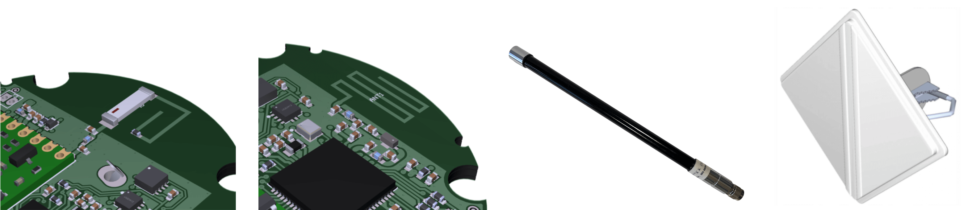
The type of antenna used has an important effect on working range. The most common antennas in modern IoT devices fall into four main groups. These are:
a) chip antennas are small, and soldered directly to the PCB and require only a matching circuit and a well designed PCB to work properly. Chip antennas are optimised to work in one chosen direction. These antennas are very popular for miniaturisation — they allow significant size reductions at the expense of slightly lower range.
b) PCB antennas are formed from PCB tracks. They are small, and cheap to make. These antennas can be made directly on the device PCB, or as a separate element connected through a U.FL antenna connector. PCB antennas can be customised for a wide variety of characteristics and configurations.
c) omnidirectional antennas are usually rod antennas, used mainly in gateways due to their large size. These antennas emit over long distances because they concentrate energy in the horizontal plane. They usually have IP67 rating, which allows them to work outdoors in the presence of water and dust. d) directional antennas are usually Yagi-Uda, sector or panel antennas. They are used less frequently in IoT than other types of antennas, but can be useful for applications such as distant, stationary nodes.
Range testing of the Yosensi nodes
We range-tested different types of antennas. Our measurements were conducted in a suburban area with a wide variety of buildings. The signal line passed through factories, single-family houses, and forest — see fig. 4.

Characteristics of our tests
- Gateway placement: on the building roof (height of about 10 m)
- Gateway antenna: omnidirectional IDEETRON 60 cm rod antenna with 12 dBi gain connected to the receiver with 1 m coaxial cable.
- Gateway receive sensitivity: Rx = –139,5 dBm.
- Frequency band: 868 MHz.
- Weather conditions: 25°C, no wind, no rain.
- Transmission parameters (average over a large amount of data frames): RSSI and SNR
- Node maximum output power: Tx = 14 dBm (maximum allowed by ETSI)
Range test results


At first glance, we can see that the chip antenna behaves differently from the others, due to its size and its low energy gain. The greatest ranges were obtained for antennas with high energy gain (antennas 1, 2, 3 and 4). Node transmission at 25 mW, combined with an antenna with an energy gain of 5–6 dBi, allows a range of 7 km (measured in a straight line). For maximum range, the best transmission parameters are obtained using directional antennas, owing to their strongly focused, unidirectional beams.
Our devices are very often equipped with antenna number 7. This is a very small chip antenna which, when properly tuned can achieve incredible ranges — in this case 3.5 km! Imagine a device about the size of a table tennis ball that can communicate over such a long distance, sending 40000 data frames on a single small battery — it’s amazing! We invite you to get to know our product — YO 360.
Our test confirmed that terrain type has a great impact on range. Forests significantly limited the range, which can be very seen in the diagrams (fig. 5, 6). The first location was unique place because, despite the short distance (620 m) it was behind a huge, metal-structure building. Antennas 5 and 7 show a clear effect of the metal structure. Interestingly, the measured parameters did not always decrease with increasing distance. In several cases, the transmission parameters were in fact better for the longer distances than for closer ones. This is related to the obstacles along the radio transmission line.
Summary
Our results may seem small compared to the world record, but they show how much the range is affected by the conditions in which the test is performed. In free space, only the air losses matter, whereas in real conditions there are many obstacles blocking the signal. Assuming ideal conditions, we can say that, for a range measured along a straight line of 7 km with a single gateway, we will get a coverage of 154 km². However, these are ideal conditions that cannot be achieved in an urban area. It will, however, be applicable in undeveloped areas, e.g. for monitoring soil conditions in open fields.
Our research can be summarized in the following points for increasing coverage:
- use antennas with the highest possible gain,
- place the gateway high to maximise its line of sight,
- place the node and gateway in locations not exposed to strong radio fields,
- for outdoor antennas, use good quality coaxial cables and as few connectors as possible.